DTK APB
1. Introduction
DTK APB is a single board combining a main controller and an onboard computer for mobile robotics applications. Built around a H7 series STM32, the controller can run most common flight control firmware such as PX4, Ardupilot, Betaflight and iNav. The onboard computer, being built on the i.MX8M Plus platform, allows for onboard complex applications such as real time AI, sensor integration, video processing and more. With a dual digital and analog camera input, it’s the perfect platform for the development of FPV and hybrid smart drones/robots applications. Being part of the DTK family, it is designed to work with the rest of the ecosystem and be augmented by them. Finally, the PCIe extension means APB is the perfect starting point for your wildest dreams.
2. Specifications
| Compute | i.MX8M Plus (4x or 2x Cortex-A53, ,Cortex-M7) STM32H743 (32-bit Arm® Cortex®-M7) |
| Video Machine Learning | H.265, H264 1080@60fps encoder3D GPU2D GPU NPU (2.25TOPS) |
| Memory | 4GB eMMC 4GB LPDDR4 RAM Up to 512GB micro-SD card |
| Connectivity | USB 3.0 USB 2.02x 4-lane MIPI-CSI 2AV-in/AV-out UART, I2C, CAN8x PWM – Up to 8 Motors |
| Temperature | Temp range: 0ºC – 70ºC |
| Power | 2S to 8S battery |
| Dimensions | 65 x 40 x 22.11 mm |
| Weight | 50g |
| Software | Orqa Yocto Linux BSP Orqa SDK included in Developer Program PX4ArduPilotiNavBetaflight |
3. Board overview
The main APB SOC is based on the i.MX8M Plus SOC. Additionally, the board contains an ORQA Flight controller. The SOC has the following hardware connected to it:
• Two MIPI CSI ports
– One of which has a CVBS to MIPI adapter to use with analog cameras
• ORQA analog OSD hardware connected with I2C
• HDMI to CVBS adapter to output HDMI as analog video
• DPS310 barometer
• ICM42605 IMU
The board can be powered from the External power connector (Max 40V) or the SOC USBC port. The USBC port supports power delivery up to 60 watts (5V to 20V, max 3A).
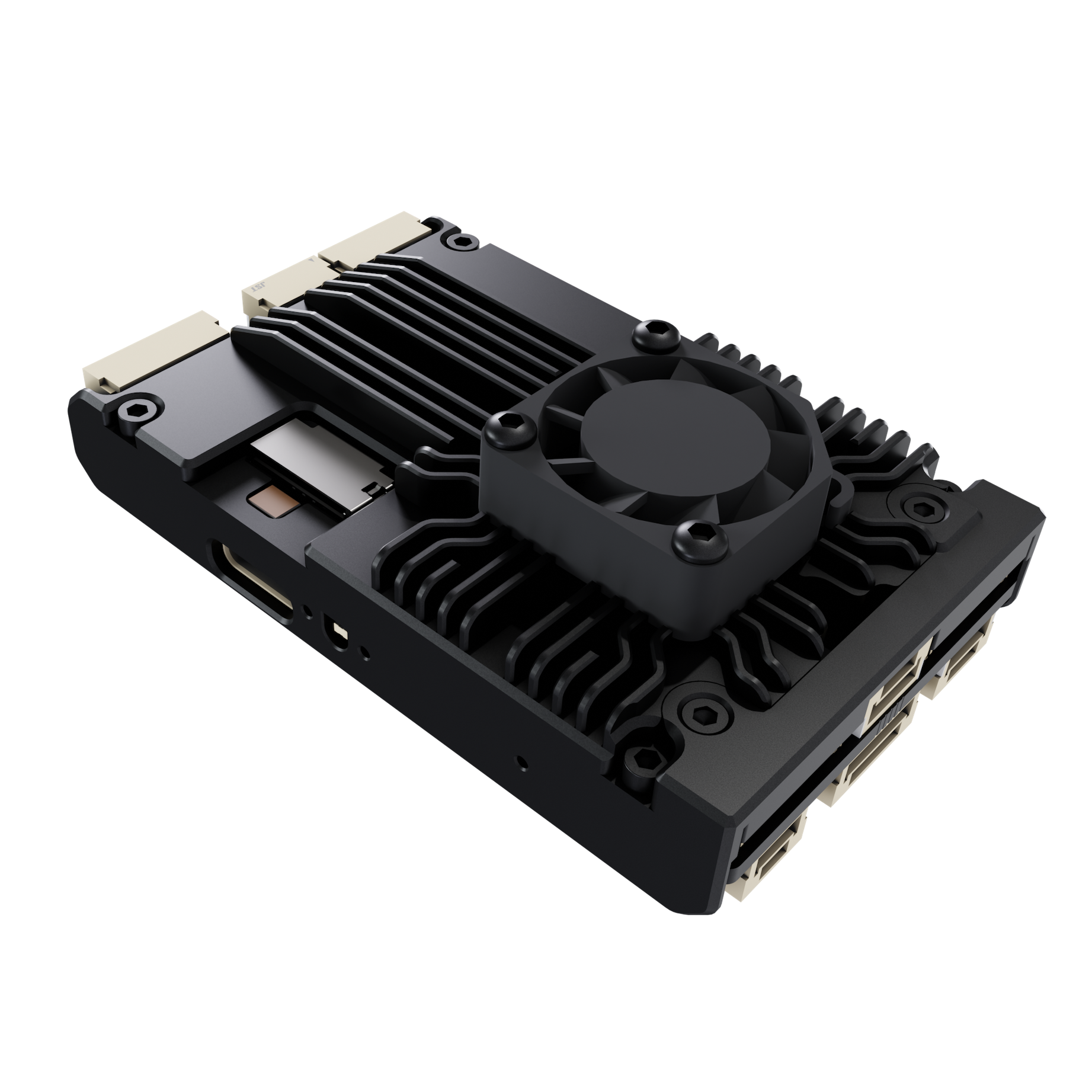
IMPORTANT: Make sure the device has airflow when stationary, as it can overheat.
4. Board layout
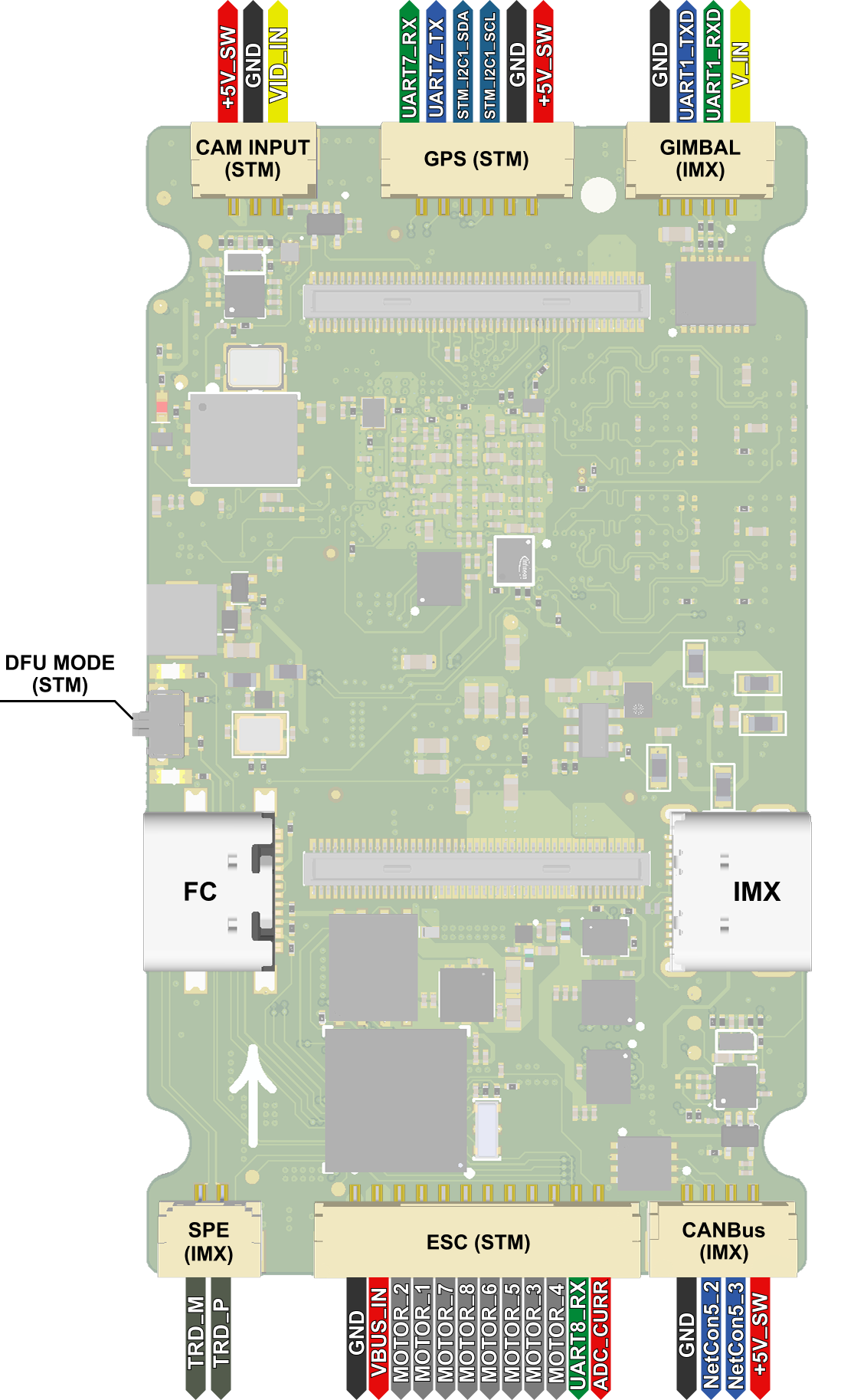
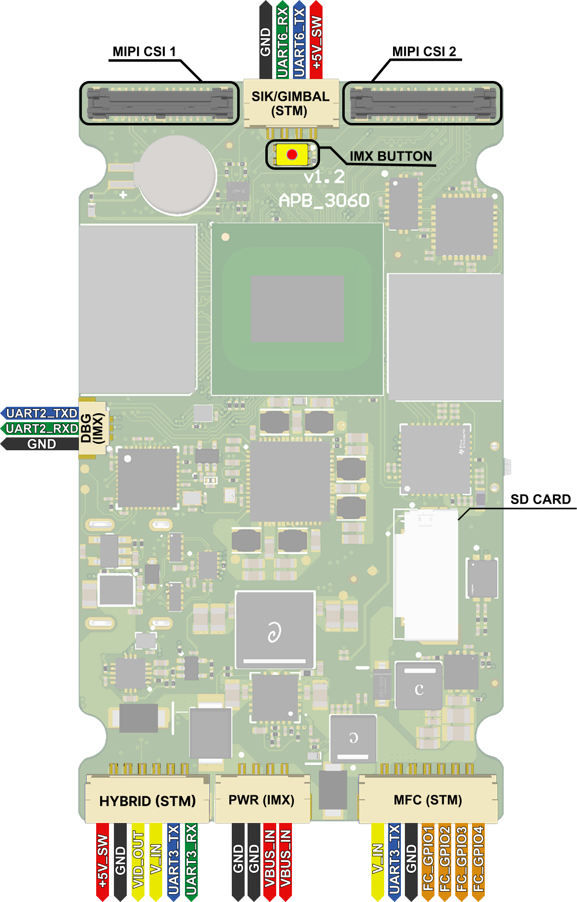
5. Signal label notes
Here are some notes regarding labels in the above images:
• V_IN is the same voltage as VBUS_IN. It can also power the board.
• IMX USB power input is routed to VBUS_IN.
• Signals coming from connectors labeled as (STM) are coming from the FC, not the IMX SOC.
6. Network
When connected to the PC via USBC, the APB will present itself as an RNDIS/USB ethernet device. It will assign itself 192.168.75.1, and assign an address to the PC over DHCP.
SSH is running on the board for easy access.
Example connecting to ssh:
ssh [email protected]Example for sending files over scp:
scp file.txt [email protected]:~A USBC ethernet adapter can also be connected. The board has a DHCP client running and will attempt to request an IP. The interface will also have a static IP of 192.168.1.75. The MAC address of the interface will start with 4E:52:51:
7. External storage
The USBC port supports USB 3.0 5Gbit devices.
The SD card slot supports SD 3.0 cards.
Supported file systems are FAT32, exFAT, and NTFS.
8. Temperature
Board temperature can be monitored by running the following command:
cat /sys/class/thermal/thermal_zone0/tempThis will print the temperature in millidegrees Celsius. The board will automatically shut down when it reaches 95°C
9. CSI 1
The CSI 1 port supports 4 lane MIPI CSI. By default it’s setup for our FPV cameras that output fixed 1280×720@60 without any external controls.
Device path: /dev/video2
10. CSI 2
The CSI 2 port can be switched between a digital input, like CSI 1, or analog input through ADV7282. See next section for details.
Device path: /dev/video3
11. Analog camera
The CVBS Camera is connected with a ADV7282 CVBS to MIPI decoder. It is outputting de-interlaced PAL video at 50Hz.
• Resolution: 720×576
• FPS: 50
• V4L2 Field modes:1 Progressive only, the ADV deinterlaces the video internally.
• Format: Depends on the ISI
12. FC
The ORQA FC is connected with the SOC over UART and CAN. The SOC’s uart (UART3) can be connected to the FC.
13. ORQA OSD
ORQA OSD drawing hardware is connected with I2C on I2C2 port (/dev/i2c-1) on address 0x0a. It emulates a max7456 interface.
14. UART
UART1 (/dev/ttymxc0) is exposed on SOC Connector 1.
UART3 (/dev/ttymxc2) is connected to an internal switch and can be routed to multiple areas.
The switch uses 2 GPIOs for selecting the path for UART3: SW1 and SW2.
| SW1 | SW2 | Connector |
| 0 | 0 | CSI 1 Connector |
| 0 | 1 | CS 2 Connector |
| 1 | 0 | FC UART |
| Switch | GPIO |
| SW1 | GPIO4_IO00 |
| SW2 | GPIO4_IO13 |
Example: the following commands will enable the UART3 to FC path:
$ gpioset gpiochip3 0=1
$ gpioset gpiochip3 13=0
15. Changing device tree
Since changing the input in CSI2 required reconfiguring the drivers, we ship 2 device trees with different configurations.
Use orqa_dt_switcher to pick and choose from available device trees.
The following device trees are available to use on this board:
• imx8mp-orqa-apb-rev2.dtb (CSI 2 digital) (Default)
• imx8mp-orqa-apb-rev2-adv.dtb (CSI 2 analog)
A reboot is required after changing device trees. These settings persist with software updates.
NOTE: The Default option inside the program deletes the custom device tree configuration
16. CAN
CAN 1 is connected to SOC Connector 2.
CAN 2 is connected internally to the FC.
17. Analog camera quirks
The camera (more specifically, the ADV7282) has an issue where it stops responding if it isn’t stopped and closed properly from a user space application. To avoid this, please ensure the stream is stopped and camera closed before exiting a program.
Here is an example of correctly stopping and closing the camera:
enum v4l2_buf_type type = V4L2_BUF_TYPE_VIDEO_CAPTURE;
if (ioctl(camera_fd, VIDIOC_STREAMOFF, &type) < 0)|
{
perror("Camera:");
}
close(camera_fd);
18. HDMI to CVBS
The analog output from the board is determined by a GPIO pin. It can be toggled with the following commands:
$ gpioset gpiochip1 20=0
$ gpioset gpiochip1 20=1
| GPIO Value | Result |
| High (1) | Analog camera passthrough |
| Low (0) | HDMI to CVBS output |
We are running wayland with the Weston compositor. The screen resolution is 720x480 at 60 Hz. You can use the following Gstreamer command to test screen output:
gst-launch-1.0 videotestsrc ! autovideosink
19. Version information
OS Version information is now located in the /etc/os-release file. The numbers that matter are contained in VERSION_ID field. The third number, and last 2 digits of the last number determine the OS version and build number. For example, in 5.10.4-3401 the OS version is 4, and build number is 01.
20. Updating image
The image is built with support for updates. There are two ways it can be updated:
• With an SD card
• Over ssh
20.1 SD Card updating
Before updating, the SD card must be formatted to FAT32, and must contain only one partition.
Download the update.orqa file and place it in the root of the drive. Insert the drive into the board and power it on.
If the update file exists on the drive, the board will boot into recovery and update.
After the update operation (success or failure), the update file will be deleted.
20.2 Updating over SSH
In case the SD card reader doesn’t work, we can manually copy the update file.
First power on the board and let it boot normally. Then copy the downloaded update.orqa file to /data/update.orqa (scp update.orqa [email protected]:/data/update.orqa).
And run orqa_update_client on the board. The program will verify the update, and if successfully verified, will print ”Update done” and reboot to perform the update.
Check the state of the LED (3.10). The status should switch from recovery to updating within 30 seconds. If not, follow procedure in ‘Updating from recovery’
The update file will be deleted after the process.
21. Image flashing
The image on the board can also be flashed from uboot using NXP’s uuu utility in case of a soft brick. Download the latest uuu utility from here: https://github.com/nxp-imx/mfgtools
If the board boots, it can be rebooted into fastboot mode to be flashed. To do that, run orqa-reboot fastboot on the board, and follow the below procedure.
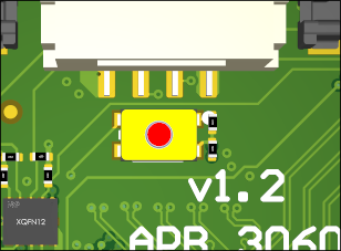
If the board doesn’t boot, it can be forced into flashing mode by pressing down the button pictured above while powering on the board.
The procedure is then as follows:
• Connect the board to your computer using a USB-C cable.
• Verify that an NXP blank device has appeared on your computer. See table below for USB IDs.
• Go to the folder with the flash.zip file
• Open a terminal and type:
uuu flash.zip
• Wait until the flashing is finished.
• When the flashing is done, the board will reboot once.
• Once the led on the board flashes three times, and stays on, the board is ready.
| Vendor ID | Product ID | Scenario |
0x35b6 | 0x0210 | Fastboot mode |
0x1fc9 | 0x0146 | Flash mode |
22. Partitions
The board has two partitions that won’t be overwritten on update: The nvram and data partitions.
The nvram partition is 64 Megabytes and designed to store configuration files, while the data partition is a general use partition with the left-over space on the flash.
When connecting the SD card, the first detected partition is mounted to /sdcard
When connecting a USB drive, the first detected partition is mounted to /usb
23. LED
The status LED on the SOC can be used to check the status of the board. It has several flashing patterns. During bootup it glows steadily, and afterwards:
• If recovery, 4 rapid flashes, then off, repeated
• If normal boot, 3 slow blinks, then it stays on
• If updating, blinking every 300ms
• When done updating, 5 rapid blinks
24. Recovery mode
The image also has a recovery mode. The board will enter recovery mode after three failed boot attempts.
The recovery mode is stored on a seperate partition with its own readonly kernel and ramdisk copy. It is also updated during a software update.
It uses the default device tree setting and ignores the changes made in ‘Changing device tree’.
24.1 Using recovery mode
A telnet server is active in recovery mode to allow access over the network. The address is set to 192.168.75.1, and the login is root without a password.
To exit recovery and attempt a normal boot, you can power-cycle the device or just reboot it over telnet.
The entire root filesystem is accessible in recovery (but not mounted), and the /data and /nvram partitions are mounted automatically.
orqa_dt_switcher is available from recovery as well.
24.2 Updating from recovery
To update (or downgrade) the software from recovery mode, insert an sd card with the update.orqa file in the root of the drive. The update program should pick it up automatically.
24.3 Checking update status
Update status can be checked from recovery using the following commands:
$ journalctl -u update-daemon.service
$ journalctl -u swupdate.service
If the board rebooted to recovery to update, and the LED hasn’t started flashing with the updating pattern (ch. ‘LED’), run the above command to check what happened.
Additionally, the update file is deleted regardless if the update was successful or not.