DTK AVP Mini
1. Introduction
The DTK AVP Mini is a member of the Orqa’s DTK System device family. The DTK AVP Mini consists of the DTK VPU Mini, Orqa’s miniature Linux-based video processor, mounted on a Carrier Board with a versatile range of I/O ports.
The AVP Mini is intended for ingesting, processing, and passing through analog video input in order to provide vision-based control input for external devices such as Flight Controllers via UART interface. The AVP is designed so it can be mounted on top of Orqa’s FC3030 series of Flight Controllers in 30 x 30 mm form factor.
The Carrier Board is also equipped with Orqa’s proprietary OSD engine, which enables generating a dynamic overlay on the analog video output.
The analog video input is split into two lines: one line is digitized and piped into the on-board DTK VPU compute for processing via the MIPI-CSI input, while the other is piped through an OSD chip before being sent to the analog video output (see the schematic on the next page).
The VPU is capable of running decent Machine Vision workloads, so it can be used as a vision processing device for applications like pixel tracking or simple classification. The VPU also drives the OSD engine, so it enables dynamic drawing and animation of text or graphics elements (e.g. bounding box markers) over the live analog video feed that is sent to the analog video output, which can then can transmitted via VTx or a similar device, without affecting the latency.
2. Specifications
| Compute | – 4 x ARM Cortex-A53 up to 1.8GHz per core – 1x Cortex-M4 core up to 400MHz |
| Video | – H.264, VP8 video encoder 1080@60fps – 3D GPU (1 shader, OpenGL ES 2.0) |
| Memory | – 4GB eMMC – 2GB LPDDR4 RAM – Up to 512GB micro-SD card |
| Connectivity | – USB 2.0 ( USB-C connector) – 4-lane MIPI-CSI 2 or AV-in/AV-out (CVBS) – 2 x UART – I2C |
| Temperature | Temp range: 0ºC – 70ºC |
| Power | 2S to 6S battery |
| Dimensions | 30 x 30 x 10mm |
| Software | – custom ultra-low-latency h.264 encoder libraries • 9ms encode / 4ms decode – custom point-to-point video streaming solution • WebRTC, RTSP , RTMP – custom point-to-point video streaming solution • WebRTC, RTSP , RTMP – custom Yocto-Linux-based OS • with custom C/C++ SDK – OpenCV C/C++, Python – Live OSD engine |
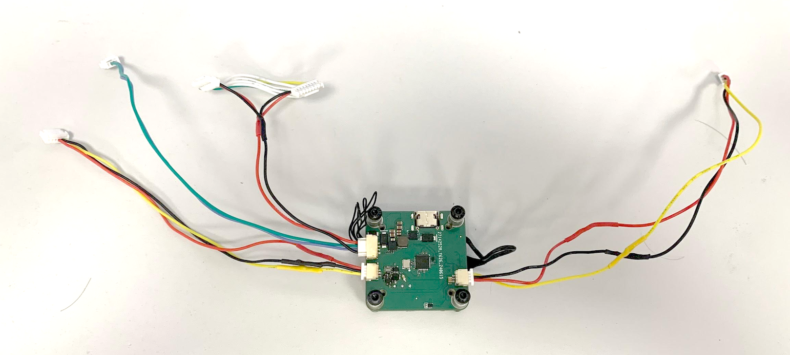
3. Wiring
Plug the three cable provided into the main unit as shown below.
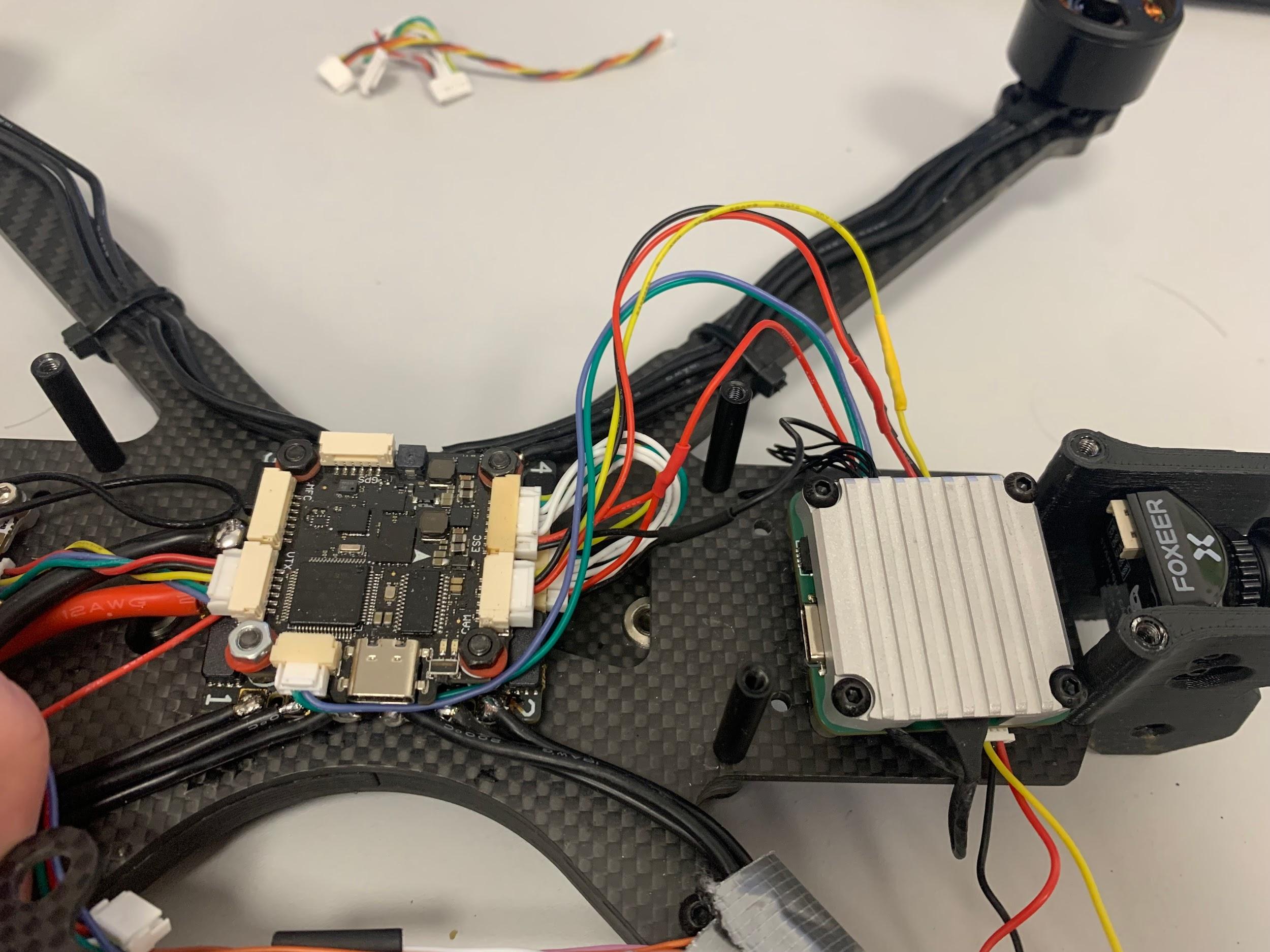
Plug the unit to the flight controller as shown below (shown here with the FPV Dev Kit frame)
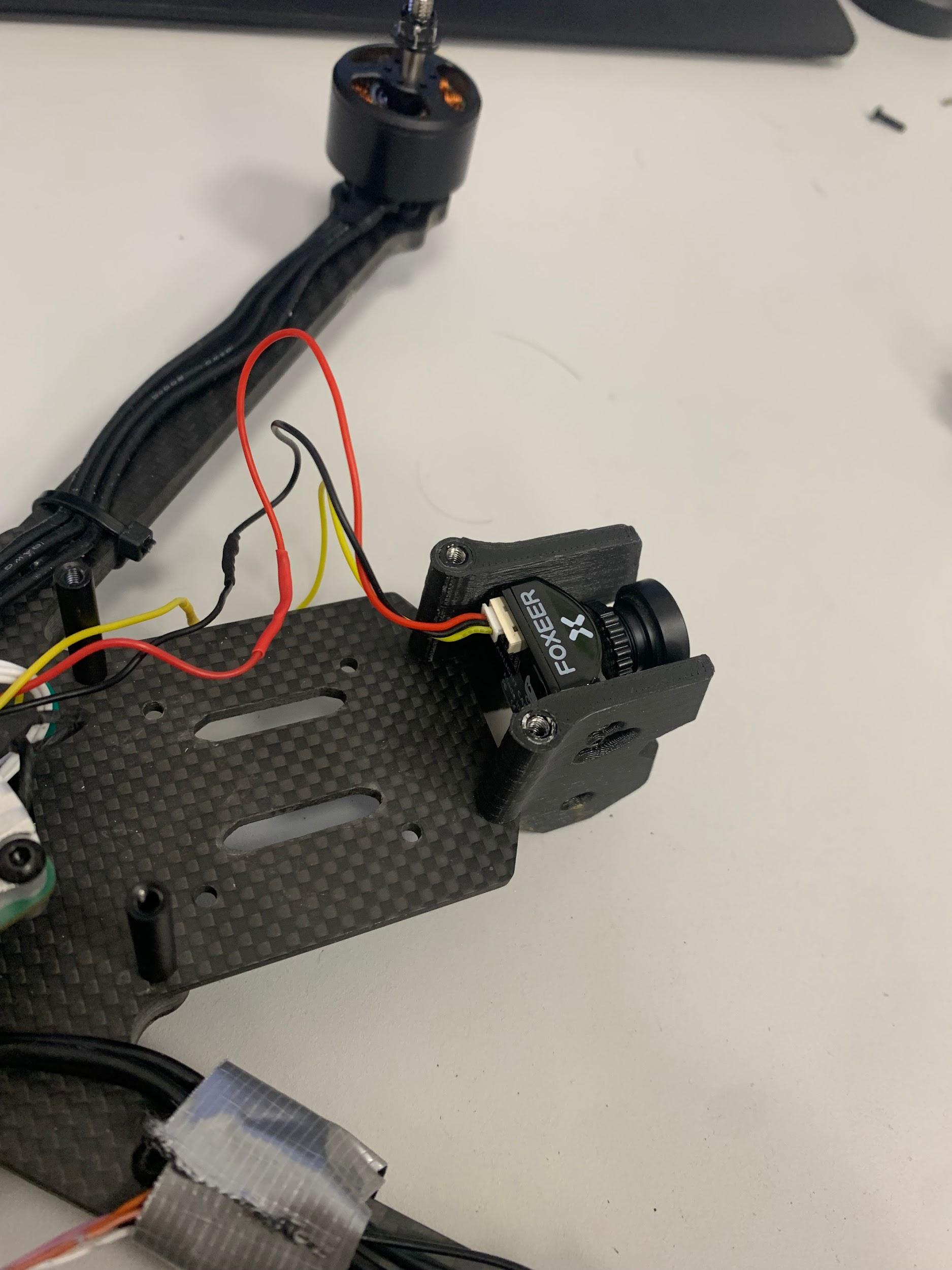
Plug the analog camera
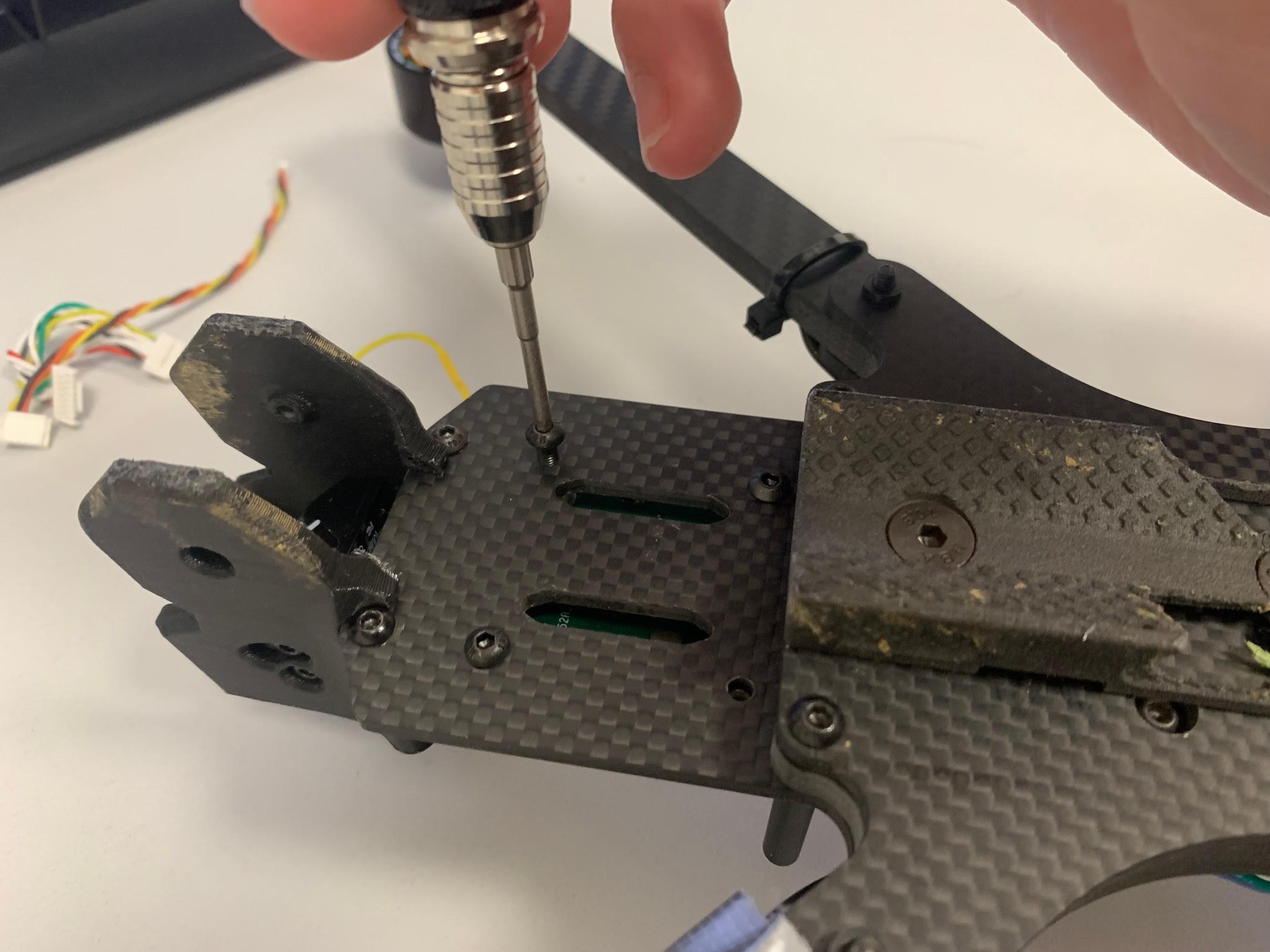
Fix the AVP to the frame through the 30x30mm mounting holes
4. Network
The SBC by default is configured as an RNDIS/USB ethernet device, and is accessible over the USBC port. The SBC assigns itself the address 192.168.75.1 and assigns an address to the PC over DHCP.
The MAC address on the interface will start with 4E:52:51:
SSH is running on the board so it can be accessed easily.
Example connecting to ssh:
Example for sending files over scp:
scp file.txt [email protected]:∼
4. External storage
By default, the USB 2.0 port is setup as a device, and doesn’t support external usb devices.
The SD card slot supports SD 3.0 cards.
Supported file systems are FAT32, exFAT, and NTFS.
5. Temperature
Board temperature can be monitored by running the following command:
cat /sys/class/thermal/thermal zone0/temp
This will print the temperature in millidegrees Celsius. The board will automatically shut down when it reaches 95°C
6. Camera
The CVBS Camera is connected with a ADV7282 CVBS to MIPI decoder. It is outputting de-interlaced PAL video at 50Hz by default.
• Resolution: 720×576 / 720×288 (Alternate)
• FPS: 50
• V4L2 Field modes:1 None (Default) / Alternate
• Format: UYVY422
• Device path: /dev/video0
If interlaced video is desired, see the alternate field mode in V4L2.
By default it is setup as progressive 720×576 at 50Hz.
7. FC
The ORQA FC is connected with the SBC board over UART. The SBC’s uart (uart1) is connected to UART6 on the FC.
8. ORQA OSD
ORQA OSD drawing hardware is connected with I2C on I2C2 port (/dev/i2c-1) on address 0x0a. It emulates a max7456 interface.
9. Additional pins
The following table describes the additional pins exposed on the board:
| 1 | UART3_RXD |
| 2 | UART3_TXD |
| 3 | I2C2_SDA |
| 4 | I2C2_SCL |
| 5 | I2C2_SDA_3V3 |
| 6 | I2C2_SCL_3V3 |
| 7 | +5V |
| 8 | +5V |
| 9 | GND |
| 10 | GND |
10. UART
UART1 (/dev/ttymxc0) is connected to the FC on the SBC’s side.
UART3 (/dev/ttymxc2) is exposed on external pins (Table 1).
11. Changing USB mode
Since we don’t have a hardware USB-C controller, the USB mode has to be changed manually. This is done inside device-trees, and multiple device trees are shipped in the software.
Use orqa_dt_switcher to pick and choose from available device trees.
The following device trees are available to use on this board:
• imx8mm-orqa-tx-usb-cvbs.dtb (Usb as host)
• imx8mm-orqa-tx-usb-cvbs-otg.dtb (Usb as device) (Default)
A reboot is required after changing device trees. These settings persistwith software updates.
NOTE: The Default option inside the program deletes the custom device tree configuration
12. Camera quirks
The camera (more specifically, the ADV7282) has an issue where it stops responding if it isn’t stopped and closed properly from a user space application. To avoid this, please ensure the stream is stopped and camera closed before exiting a program.
Here is an example of correctly stopping and closing the camera:
enum v4l2_buf_type type = V4L2_BUF_TYPE_VIDEO_CAPTURE;
if (ioctl(camera_fd, VIDIOC_STREAMOFF, &type) < 0)
{
perror("Camera:");
}
close(camera_fd);
13. Version information
OS Version information is now located in the /etc/os-release file.
The numbers that matter are contained in VERSION_ID field. The third number, and last 2 digits of the last number determine the OS version and build number. For example, in 5.10.4-3401 the OS version is 4, and build number is 01.
14. Updating image
The image is built with support for updates. There are two ways it can be updated:
• With an SD card
• Over ssh
15. SD Card updating
Before updating, the SD card must be formatted to FAT32, and must contain only one partition.
Download the update.orqa file and place it in the root of the drive.
Insert the drive into the board and power it on.
If the update file exists on the drive, the board will boot into recovery and update.
After the update operation (success or failure), the update file will be deleted.
16. Updating over SSH
In case the SD card reader doesn’t work, we can manually copy the update file. First power on the board and let it boot normally. Then copy the downloaded update.orqa file to /data/update.orqa (scp update.orqa [email protected]:/data/update.orqa).
And run orqa_update_client on the board. The program will verify the update, and if successfully verified, will print ”Update done” and reboot to perform the update.
Check the state of the LED. The status should switch from recovery to updating within 30 seconds. If not, follow procedure in ‘Checking Update Status’
The update file will be deleted after the process.
17. Image flashing
The image on the board can also be flashed from uboot using NXP’s uuu utility in case of a soft brick. Download the latest uuu utility from here: https://github.com/nxp-imx/mfgtools
If the board boots, it can be rebooted into fastboot mode to be flashed. To do that, run orqa-reboot fastboot on the board, and follow the below procedure.
If the board doesn’t boot, it can be forced into flashing mode by pressing down the button pictured above while powering on the board.
If the LED stays off after powering the board on, the board is in flashing mode, and the button can be let go.
The procedure is then as follows:
• Connect the board to your computer using a USB-C cable.
• Verify that an NXP blank device has appeared on your computer
(ID: 0525:a4a5 in fastboot, 1fc9:0134 in flash mode)
• Go to the folder with the flash.zip file
• Open a terminal and type:uuu flash.zip
• Wait until the flashing is finished.
• When the flashing is done, the board will reboot once.
• Once the led on the board flashes three times, and stays on, the board is ready.
18. Partitions
The board has two partitions that won’t be overwritten on update: The nvram and data partitions.
The nvram partition is 64 Megabytes and designed to store configuration files, while the data partition is a general use partition with the left-over space on the flash.
When connecting the SD card, the first detected partition is mounted to /sdcard
When connecting a USB drive, the first detected partition is mounted to /usb
19. LED
The status LED on the VPU module can be used to check the status of the board. It has several flashing patterns. During bootup it glows steadily, and afterwards:
• If recovery, 4 rapid flashes, then off, repeated
• If normal boot, 3 slow blinks, then it stays on
• If updating, blinking every 300ms
• When done updating, 5 rapid blinks
20. Recovery mode
The image also has a recovery mode. The board will enter recovery mode after three failed boot attempts.
The recovery mode is stored on a seperate partition with its own read-only kernel and ramdisk copy. It is also updated during a software update.
It uses the default device tree setting and ignores the changes made in ‘Changing USB Mode’
21. Using recovery mode
A telnet server is active in recovery mode to allow access over the network. The address is set to 192.168.75.1, and the login is root without a password.
To exit recovery and attempt a normal boot, you can power-cycle the device or just reboot it over telnet.
The entire root filesystem is accessible in recovery (but not mounted), and the /data and /nvram partitions are mounted automatically. orqa_dt_switcher is available from recovery as well.
22. Updating from recovery
To update (or downgrade) the software from recovery mode, insert an sd card with the update.orqa file in the root of the drive. The update program should pick it up automatically.
23. Checking update status
Update status can be checked from recovery using the following commands:
journalctl -u update-daemon.service, andjournalctl -u swupdate.service for more details.
If the board rebooted to recovery to update, and the LED hasn’t started flashing with the updating pattern (ch. 2.8), run the above command to check what happened.
Additionally, the update file is deleted regardless if the update was successful or not.